The field of mold processing is inseparable from CAM software, not only because complex profiles cannot be completed by manual calculation, but also the key factor is to improve product quality and processing efficiency. Making full use of CAM platform is one of the most effective means. At present, we have seen the situation in which CAM and mold processing mutually promote each other. At the beginning of the development of CAM software, we focused on solving problems that can and cannot be. Today, this stage is being pursued, and higher requirements are placed on processing efficiency and product quality. With the diversification of processing methods and the rapid development of numerical control equipment, new requirements have been put forward for the application scope of CAM software. Here we analyze how to better apply CAM software through the two aspects of improving efficiency and quality in mold processing.
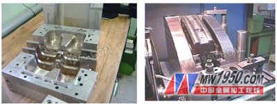
In the mold processing, due to the characteristics of long processing time, high added value of products, and small batch size, the efficiency in mold processing has become the focus of attention. Since in the finishing process, the material removal rate per unit area is almost the same regardless of the processing trajectory selected, the most obvious effect is to effectively shorten the roughing time. In order to create a good cutting condition for finishing, the roughing should remove the material as much as possible to ensure a uniform margin. In general, in the roughing process, to increase the efficiency, the larger diameter tool should be used as much as possible, and then the small diameter tool is used for the residual material processing. Such a large-to-small selection of tools for hierarchical partitioning requires flexible processing of residual materials. For example, sub-level cutting and residual material processing in Edgecam can flexibly meet this need. Sub-level cutting refers to a method of refining a large residual step on the surface of the profile by using the same tool for roughing the deep depth of the cut. This method is formed by directly processing the smaller diameter tool directly. Compared with the processing surface, the processing efficiency can be effectively improved. In addition, when roughing the residual material, when the small-diameter tool is used to machine the area where the previous large-diameter tool cannot be processed, the residual material of the previous large-diameter tool can be automatically recognized and the tool path can be generated, and the residual material can be processed according to the situation. Select a sub-level cut or a defined machining area. These two methods effectively ensure the high quality and high efficiency of the tool path generated by rough machining. From the following, we know from the processing of two actual processing of the tires that the amount of roughing material removed in the mold processing is far greater than the finishing; therefore, to improve the processing efficiency should first be done in the roughing process optimization. Secondly, in the whole process of mold processing, the time spent on programming is also a link that should be concerned.
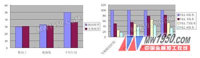
In the programming process, we spend mainly two aspects, one is the perfection of the model, including the repair of the model, the generation of auxiliary lines and faces; the second is the calculation time for generating the tool path. Nowadays, CAM software is emerging one after another, and the classification methods are also diverse. Here, the software is classified from the perspective of surface machining and solid machining. The reason is that classification of CAM from the perspective of the type of model being processed is the most essential and core entry point. At first, all CAM software is based on surface machining as the core, and the tool path is generated by calculating the plurality of surface patches that make up the model. In the late 1990s, with the rapid development of 3D solid CAD, many CAM software can program the solid model, but the basis for calculating the tool path is not the solid model itself, but the elements such as the point line surface extracted from the solid model. Therefore, it is still essentially a surface machining, at best, a processing entity. Solid machining refers to the generation of tool trajectories based on the physical model. Most of these CAM software emerged after 95 years. After 2000, with the development of computer hardware and the development of the Windows platform, CAM software has been rapidly developed. For example, now Edgecam, CAMworks, etc. The characteristics of this kind of software are from the CAD to CAM process, based entirely on the solid model, there is no model conversion and data loss, so there is no need to repair the model. Not only can the errors and omissions caused by the artificial patching model be effectively avoided, but also the time can be greatly saved. However, since the amount of information in the solid model itself is more complete than the surface model, the amount of calculation increases accordingly, and an effective algorithm can solve this problem. For example, we did some tests with Edgecam and were pleasantly surprised to see that the computation time for the solid model was substantially improved by the optimization of the algorithm. The following is a comparison chart. We can see that the calculation time of the solid model under the same conditions is almost the same as that of the surface model (see Figure 1). Here we see a very interesting phenomenon. In some cases, the calculation time of the surface model is more than the calculation time of the solid model, which is related to the complexity of the surface model construction and the size of the model. Taking the medium-sized model as an example, in the process of calculating the tool path, when the hundreds of patches that make up the model are used as the basis for calculation, it takes some extra time to process the boundary of the surface; Boundary processing is much easier, so it saves a lot of computation time, which is the reason for this phenomenon. In addition, we can see the improved computing performance in the process of updating the Edgecam version. We can also see this change by comparing the horizontal processing of the same processing method in different versions (see Figure 2).
The quality of the profile in the mold processing is the core of the entire mold. Therefore, how to improve the quality of profile processing is the top priority for improving product quality.
Choosing reasonable machining parameters and tools is an important part. Within the allowable feed and speed range of the machine, it is important to select the appropriate machining parameters for the profile based on the properties of the material being machined and the hardware of the machine tool. For example, when finishing a profile of a brass electrode (see the figure below), we use a 2 mm diameter end mill with a speed of 12,000 rpm. The feed rate is 2000 mm/min. Even if the tool path is set very dense, the resulting surface quality is not ideal. When the spindle revolution is reduced to 6000 rpm, the surface quality of the finished profile is very good. The reason is that the influence of tool flutter on the formation of the profile quality during the finishing process has far exceeded the influence of the tool path on the profile quality. Therefore, in the process of processing, the process factors to be considered are not only limited to the material to be processed and the tool, but also need to consider the influence of non-negligible factors including tooling and machine tools.

In addition to selecting reasonable processing parameters, the density and pattern of the tool path are two key factors in determining the quality of the profile during programming. In theory, we can get better surface quality by encrypting the tool path, but as the tool path is encrypted, the processing time is extended, which reduces the processing efficiency. In the process of finishing the profile, if the density of the tool path is too large, the cutting amount per tooth of the tool is too small, and the effect of the machining is not ideal, so the density of the tool path is not as small as possible, according to the actual It is very important to make a decision. The pattern of the tool path is determined by the programming strategy of the programming software. Each CAM software has multiple machining strategies for generating tool paths. The range of each machining strategy and the style of the generated tool path are different. The combination of strategies results in efficient and high quality toolpath styles. For example, the tool path generated by the parallel line cutting method is popular among programmers because of its high stability and handling. However, the tool path of parallel line cutting is not very good for the processing of steep areas. In general, there are two ways to deal with it. One is to avoid such a situation. We can identify and avoid the processing parameters. Steep areas generate tool paths, and steep areas can be processed using other machining tracks. Another way is to take a change in the direction of the cut in the steep area. Both of these methods are perfect means for the shortcomings of the parallel line cutter path.
In short, for the efficiency and quality of the mold processing, not only from the selection and use of machine tools and tools, but also from the application of CAM software to give a deep understanding and understanding, can not only stay in the product, It is necessary to obtain greater product added value and production efficiency from a faster and better perspective.
Door panel: door panel is made of stainless steel 304 with no frame. Core materials are paper honeycomb, aluminum honeycomb, PU, EPS and etc. The installation sites of door lock, door closer and hinge are reinforced with square tubes of more than1.5mmthickness which are compression moulded by special technology.
Door frame: it is made of completely stainless steel 304. The connection types with wallboards are double-clip type and aluminum connection. The former is applied mostly to machine made wallboard and the latter hand made wallboard. The accessories are double window and lift type sweeping bar. The lock can be famous door lock or the owners can select lock brands themselves.
Specification: common sizes 800X2100, 900X2100, 1500X2100 or1800X2100, can customize to customers` requirements, the materials can be selected according to customers` requirements such as306Lor other special materials.
Features: the stainless steel 304 door we produced are of elegant appearance, sturdy and durable, acid and rotting resistance and thermal insulation. It is the first choice for high-end projects at home and engineering concerning foreign affairs that requires for anticorrosion and high quality such as electronics factory and food factory
Hospital Sliding Door,Hospital Automatic Sliding Door,Hospital Sliding Glass Door,Hospital Sliding Ward Door
Shenzhen Hongfa Automatic Door Co., Ltd. , https://www.selfrepairinghighspeeddoor.com