CAD drawings are indispensable in the 3D CAD design process. This 3D CAD technique mainly shares the practical tips in the 3D engineering drawing module. Through the easy-to-use and easy-to-use features of Zhongwang 3D, you can quickly master these CAD operations. Zhongwang 3D provides more intelligent drawing operations and supports a variety of standard CAD drawings. By familiarizing with the CAD drawing skills of this article, it is possible to achieve a multiplier effect for engineers to quickly produce CAD drawings!
1. Custom frame
The frame is required for each drawing. In Zhongwang 3D, you can use the normal mode, draw lines, add text, add pictures, etc. in the drawing module to complete the frame, but this method is very inefficient. For the company, it is often already in the two-dimensional CAD, such as Zhongwang CAD, there are related standard frames, how to use directly without repeating labor? Zhongwang 3D gives a very good solution - direct import (Figure 1)!
First, create your own template and rename it, such as my A4(H) (H in the extension represents the A4 landscape drawing), then modify the frame size to the desired size (Figure 2).
You can easily convert an existing frame template into a 3D drawing template (Figure 3) by entering the previously saved DWG drawing and moving the position.

figure 1
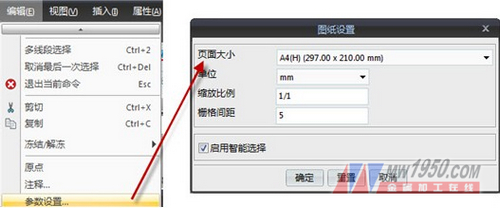
figure 2
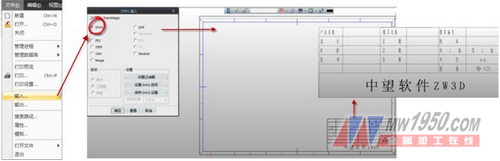
image 3
2. Convert the spline to a straight line and an arc (Figure 4)
In mold design or mechanical design, some spline curves often appear, and the position of these spline curves requires wire cutting (such as inserts or electrodes in the mold). However, most wire cutting machines currently do not recognize splines.
The current method commonly used in factories is to enlarge the DXF or DWG drawings by the wire cutter operator, and then draw straight lines or arcs by hand (because the wire cutting machine can only recognize straight lines or arcs), try to approximate the sample. Curve. The workload is large and there are errors.
And it can be easily handled by the "convert to arc/line" function of Zhongwang 3D! With this function, the spline can be converted into a straight line or an arc, and the tolerance line can be used to accurately obtain the programming line of the required precision.
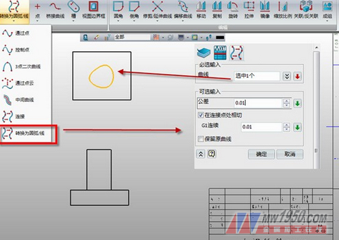
Figure 4
3. Quick labeling
Marking is one of the most time-consuming tasks in the plot. In terms of labeling, Zhongwang 3D can make baseline labeling, continuous labeling, coordinate labeling and other label types very quickly, which can greatly improve the efficiency of engineers' drawing. And the operation of the relevant commands is very simple (Figure 5, Figure 6, Figure 7).

Figure 5

Image 6

Figure 7
4. Order size
In terms of mechanical design or mold design, the parts need to be machined. To process, it involves the size of the ordering material, and it is necessary to order a large amount of material to save costs. If the part is a regular rectangle or a circle, the order size will be better. But often in the actual design process, the parts are mostly irregular. In this regard, Zhongwang 3D provides a very efficient solution for quickly obtaining the required billet size for the part. At the same time, this size can be automatically obtained when the BOM is exported, which improves the overall design efficiency (Figure 8).
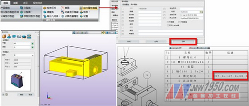
Figure 8
5. Symbol library
In 2D CAD, everyone should be familiar with the block. Blocks play a very important role in the graphics rendering process. So is there a similar function in the 3D engineering drawing? The answer is yes. There is a function of the symbol library in Zhongwang 3D. Users can make technical descriptions, special symbols, etc. used in the work as symbols, define insertion points, and add them to the symbol library (Figure 9, Figure 10).
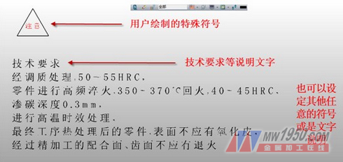
Figure 9
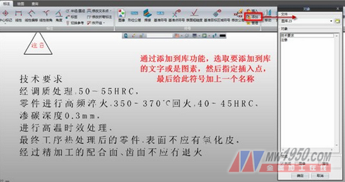
Figure 10
These symbols added to the library are saved in a part, and then this part ("gallery.z3" in the example) is saved to any location on the hard disk. In the configuration options, the symbol library path is pointed to the saved file, and the function of using the "insert" symbol in any subsequent drawing can use the previously created symbol or text description, which can effectively improve the drawing efficiency. (Figure 11).
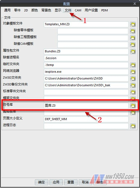
Figure 11
After familiarizing yourself with the 3D CAD engineering drawing skills of Zhongwang 3D, you are welcome to learn more and use it more quickly to master the operation of 3D CAD software. You are also welcome to visit the 3D CAD community () to discuss 3D. CAD design skills to jointly enhance 3D CAD design capabilities!
The Peristaltic Pump can be used in liposuction surgery, in the process of swelling anesthesia, used to deliver saline.
The definition of swollen anesthesia is to infiltrate into subcutaneous adipose tissue by ultra-low concentration, high-dose, a large-volume local anesthetic (currently used lidocaine) as an anesthetic method for liposuction.
Swelling anesthesia was first proposed by Klein in 1987. It is also called [over-perfusion anesthesia". A large amount of solution containing adrenal and lidocaine is stably perfused into the skin through a peristaltic pump, causing edema and cell tissue gap in the subcutaneous tissue and its structure. The small blood vessels are separated and pressed to be locked, thereby achieving the effects of local anesthesia, pain relief, hemostasis, and tissue separation.
Swollen anesthesia can be used as separate local anesthesia or combined with general anesthesia or regional anesthesia.
The advantage of peristaltic pump in swelling anesthesia:
1, easy operated, non-contamination
2, foot pedal control ,safety & reliability
3, adjustable speed and left/right direction optional
4, Power-down memory function

Peristaltic Saline Pump,Liquid Peristaltic Infusion Pump,Liposuction Peristaltic Pump,Medical Treatment Peristaltic Pump
Baoding Chuangrui Precision Pump Co., Ltd. , https://www.crprecisionpumps.com