Second, real-time control system represented by flat-panel industrial integrated computer
The basic function and form are the same as the microprocessor controlled embedded real-time control system. The biggest difference is that the output display screen is changed from character display to computer image display (see Figure 3).

Figure 3 shows the real-time control system represented by a flat-panel industrial integrated computer
Hardware composition
(1) A microprocessor control board with CPU, memory, input and output interfaces is required on the IF power supply.
(2) Configuration of flat-panel industrial integrated computer: CPU, memory, video display card, hard disk, USB interface, touch or non-touch display, and conventional computer configuration such as input and output interface, microprocessor control board needs to be One-piece computer for data communication.
2. Input and output signals
It has the same input and output contents as the microprocessor real-time control system.
The contents of the above two induction melting furnace real-time control systems focus on the control and management of the intermediate frequency power supply and the electric furnace itself. With the continuous development of the control technology of the foundry industry, the real-time control system of the induction melting furnace needs to be closely related to the electric furnace. Manage. As a modern foundry, it is necessary to carry out real-time monitoring and management of the main equipment in the factory, such as the batch feeding system, electric furnace and molding line. This also requires the induction melting furnace real-time control system in addition to its own management, but also The data is sent to the upper computer to enable the computer in the foundry to receive data from the real-time control system of the induction melting furnace.
Based on this purpose, the induction melting furnace real-time control system needs to develop a wider coverage control system, requiring an additional industrial computer to handle the above-mentioned control and management of the intermediate frequency power supply and the electric furnace itself, and generate various melting furnaces and The report of the time period; the calculation management of the added additive; the spectral analysis data of the iron component of each heat is received and recorded in the corresponding report. At the same time, a communication port is reserved for the foundry to manage the computer needs, and the data is read from the induction melting furnace real-time control system.
Third, the real-time control system represented by the industrial computer
The real-time control system represented by the industrial computer is shown in Figure 4.
Hardware composition
(1) A microprocessor control board with CPU, memory, input and output interfaces is required on the IF power supply.
(2) Industrial computer configuration: CPU, memory, video display card, hard disk, DVD-ROM, keyboard, mouse, USB interface and display, as well as multi-serial input and output interface card and other computer configuration, industrial computer needs and micro-processing The control panel, the weighing device and the temperature measuring device perform data communication.
(3) Generally, a closed computer control cabinet is additionally provided, which includes some data transfer interfaces of the computer and the microprocessor control board, the weighing device and the temperature measuring device.
2. Input signal
(1) Operating parameters of the intermediate frequency power supply.
(2) The weight of the electric furnace.
(3) Temperature signal. Includes: 1 thermocouple signal for the oven. 2 iron liquid instantaneous contact thermocouple signal. 3 electric furnace cooling water temperature measurement thermocouple signal.
(4) The signal of the iron component spectrometer.
3. Output signal
The output signal mainly has parameters for monitoring and displaying the operation of the power supply; diagnosis and display of faults; receiving control signals linked with other devices; and printout.
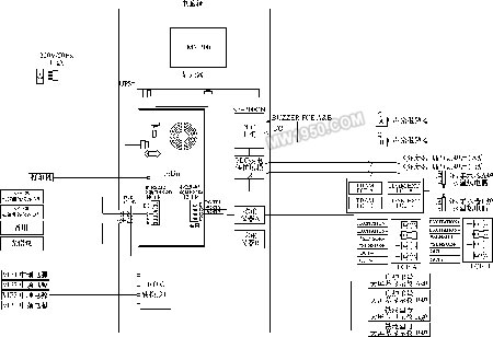
Figure 4 shows the real-time control system represented by the industrial computer
Previous Next
307 Bore Type Thread Insert,Threaded Hole Insert 307 Self Tapping,307 Type Self-Tapping Thread Insert,307 Thread Insert
Shenyang Helisert Technology Co., Ltd , https://www.helisert.com