2.1.2 Establishing the blade surface

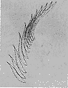
Figure 2 Blade curve described in cross section
Fig. 2 The vane curve described by section
1) In this case, due to the large number of section curves, the double patch is used to construct the surface, and the above is the use of the Curve Curves option and the Parameter modeling method in the Creat→Free Form Feature. The blade section spline creates a curved surface.
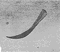
2) Using the end points of the water outlets of each cross-section spline, create two curves on the front and back sides of the blade respectively, and establish a ruled surface by using the Ruled option of Creat→Free Form Feature;
3) Use the Sew option in Creat→Feature to stitch the generated spline surface and the straight edge of the water edge into one piece, as shown in Figure 3.

Figure 3 Surface modeling of the blade
Fig. 3 The surface modeling of vane
2.2 The shape of the wheel body
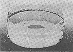
In manufacturing, an axial flow runner is formed by a set of equiangular blades attached to a runner body having an upper crown and a lower ring. According to the shape of the blade, the rotor body can be shaped according to the structural requirements. The edge connecting the front side of the blade with the upper crown and the lower ring is projected onto the XZ screen, and the projection line is used as a bus bar to rotate around the Z axis to generate a rotating surface, and the front and back sides are trimmed to obtain a "band" rotating surface. The sketch function makes the busbar. The Feature→Body of Revolution is used to create the upper and lower rings on the wheel body.

Figure 4 Top and lower ring shape of the runner
Fig. 4 The upper crown and lower ring modeling of turn wheel-body
2.3 The overall shape of the runner
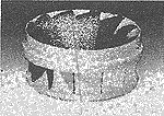
Combine the total number of blades arranged on the circumference of the blade made by the above method with the rotor body, and use Edit/Transform→Rotate About a line→Copy (edit/transform→rotate around the fixed axis→copy) to The method of requesting the number of blades is combined with the upper crown and the lower ring United on the rotor body to form an integral runner as shown in FIG. 5.

Figure 5 overall shape of the runner
Fig. 5 The whole modeling of turn wheel
Previous Next
soap rack,soap holder,soap stand,stainless steel soap holder,steel wire soap stand,etc.Let your bathroom become more simple and upscale!Applicable to families, hotels, home stay and other places to use.
304 stainless steel never rust, will easy to clear, it's also very durable!
we are 15 year factory, we had big engineer team, and strong production line, can give you good serve and quanlity. Welcome to cooperation!
Soap Rack,Soap Holder,Soap Stand,Stainless Steel Soap Holder,Stainless Steel Wire Soap Stand
Shenzhen Lanejoy Technology Co.,LTD , https://www.brassinsert.net